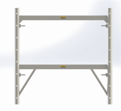
Load testing on Vertical Members of H-frames
Load testing on Vertical Members of H-frames
H-frames vertical pipe 70 mm OD and 1.2 m in length is tested and easily takes a load of 7.6 mt. for 1 mm lateral deflection. So in H-frame, we have braced vertical pipe with horizontal support @ 610 mm henceforth the load taking capacity of frames goes up to 12 mt. Tower load taking capacity depends upon the extended length of screw jack and extension tube opening at top and bottom.

H Frame Tower Capacity with Screw Jack & Extension Tubes
| Extension Combination | Safe Load | ||
|---|---|---|---|
| Ext Tube Open | 2 Screw Jack | Max Extension | 1220 mm Extension Tube + Screw Jack Extended 305 mm |
| mm | mm | ||
| 200 | 600 | 800 mm | 5474 Kg |
| 350 | 600 | 950 mm | 5058 Kg |
| 500 | 600 | 1100 mm | 4432 Kg |
| 660 | 600 | 1260 mm | 4170 Kg |
| 80 | 600 | 1400 mm | 3910 Kg |

Imp Note: Total calculations and layouts shall be provided by our design team receiving your RCC Drawings.
What you should know before Erection
- Know your floor to floor height.
- Know the height of frames available.
- Know the length of screw jacks available.
- Know the length of extension tubes available.
- Know the length of your primary and secondary beams. Check if the section is shown (width and depth of the beam section) in the formwork drawing is available on your site.
- What is the arrangement shown in the formwork drawing,
- Mark the beam supporting grid on the base slab.
- Note the areas requiring any special treatment. Note elements at different levels.
- Start the erection in the given sequence.
Working Procedure for the System
- Calculate how much the screw (base screw and top screw) need be opened. This depends on Floor to Floor height, slab thickness, plywood thickness, depth of primary and secondary beams, no. of frames required one on top of the other (as per the available heights of frames), no. of extension tubes of known lengths. The overlap between screw jack and extension tube and extension tube and frame leg also needs to be considered.
- Mark the points on the base slab where exactly the verticals should be placed.
- First place the screw jack (4 nos ) as per the frame dimension and the distance between the frames as per the design
- Open the 4 screws equally, slightly higher than the required length. It is easier to lower the screws than raise, for an adjustment. Lowering or raising should also be done equally on all screws. The base of the extension tube or frame should be at the same level. This will also ensure the plumb of the vertical members.
-
- If the extension tube is to be inserted over the the base screw at its lower end and has the frameles coming over it at its upper end, the extension tube should be connected with the Extension U Clip. The Extension U Clip should pass through two holes of the extension tube It should not happen that the one arm of Extension U Clip passes through only one hole of the extension tube and one arm passes through a hole of Frame Leg.
- Erect the first level of frames, with an extension tube and pin in place.
- If another level of frames is to be added, a coupling pin has to be inserted in the lower frame leg and the upper frame less comes from above and rest perfectly on the bearing clip of the coupling pin.
- The Extension U Clip should also pass through the two holes of the coupling pin.
- If the extension tube is to be inserted over the the base screw at its lower end and has the frameles coming over it at its upper end, the extension tube should be connected with the Extension U Clip. The Extension U Clip should pass through two holes of the extension tube It should not happen that the one arm of Extension U Clip passes through only one hole of the extension tube and one arm passes through a hole of Frame Leg.
-

We supply our products in Pune, Kolhapur, Mumbai, Navi Mumbai, Nagpur, Nashik, Aurangabad, Sangli, Satara, Jalgaon, Karad and various nearby cities of Goa and Karnataka.
Get In Touch Today
Please fill this form for a PROMPT QUOTE.